
Tool · Rectangular column
Rectangular column biaxial P–Mx–My: the full surface, continuous D/C.
Nominal and design strengths are computed at every neutral-axis angle and assembled into a three-dimensional interaction surface; every load case gets a demand/capacity ratio independent of the sampling angle.
Tool screen
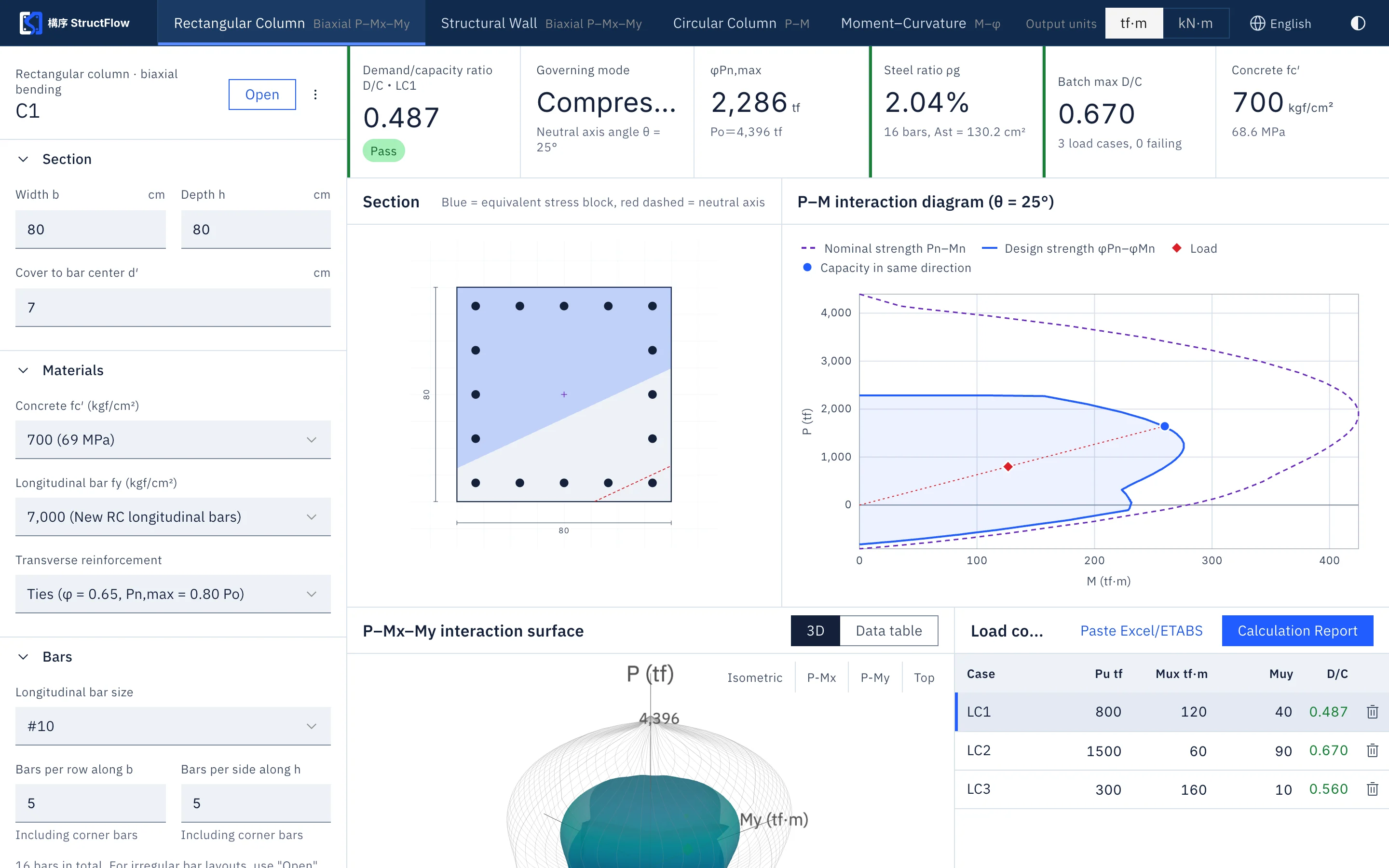
Calculation basis
Concrete is modeled with the equivalent rectangular stress block, with parameters modified for high-strength concrete according to New RC research; the compression zone is computed exactly, with no fiber discretization error. The strength reduction factor and axial load limit depend on the confinement type (tied or spiral). Check results are presented as a continuous demand/capacity ratio.
Inputs and outputs
| Item | Description |
|---|---|
| Section | Width b, depth h; optionally two centered steps (corresponding to the original h1 b1 h2 b2 h3 b3) |
| Materials | Concrete fc′ (kgf/cm², with MPa conversion); longitudinal bars fy, including New RC high-strength grades |
| Reinforcement | Bar size and number of bars per row along b and h (including corner bars), or arbitrary positions specified in a txt file |
| Confinement | Tied (φ 0.65, Pn,max 0.80Po) or spiral (φ 0.75, Pn,max 0.85Po) |
| Sampling | Neutral-axis angle θ every 5° (same as the original) or every 1° |
| Output | φPn,max, Po, reinforcement ratio ρg, controlling mode, D/C, 3D surface, P–M curve, data table, calculation report |
Scope of application
Put your column section to the test.
Sign up free with a SUHUL EIP account for a 14-day free trial, no credit card required.