
Tool · Structural wall
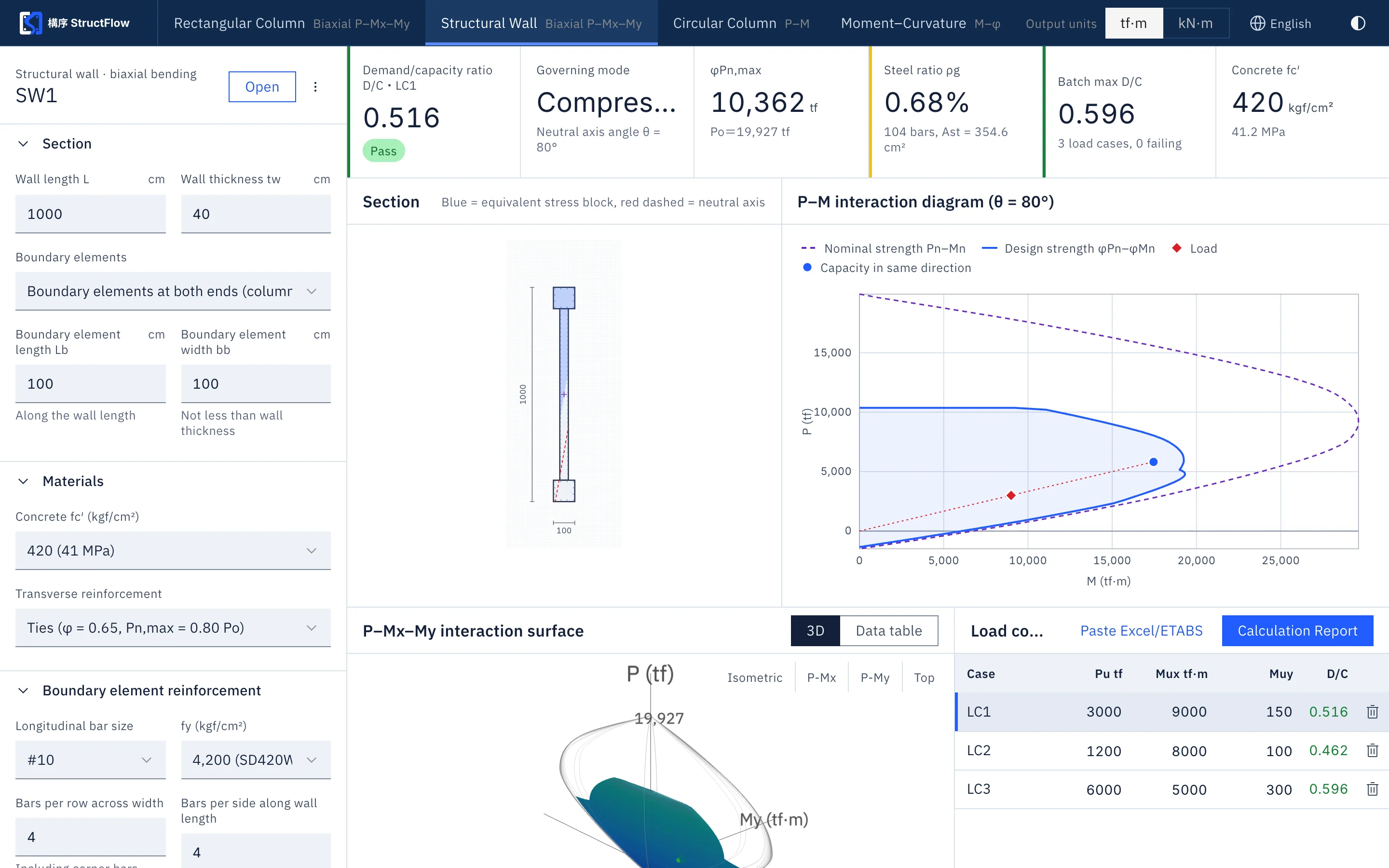
Structural wall biaxial P–Mx–My: parametric input, matching the original point by point.
Describe the section by wall length, thickness, two boundary elements, boundary element perimeter reinforcement, and double-layer web bar spacing. All bar positions are generated automatically, and the biaxial surface and check workflow of the rectangular column are reused.
Tool screen
P–M diagrams for the strong and weak axes
The figure below is taken from the actual calculation results of the calculation core for the default structural wall: design strength curves for θ = 0° and θ = 90°. They show the large difference in wall capacity between the strong and weak axes, which is exactly why a biaxial check cannot be omitted.
Parametric input
| Parameter | Description |
|---|---|
| Wall length L, thickness tw | Outer dimensions of the wall |
| Boundary elements | Each end can be switched on or off; size and perimeter reinforcement are set independently |
| Web bars | Double layer, arranged automatically by spacing s, with the first row s/2 from the boundary element |
| Materials and confinement | Same as the rectangular column: fc′, fy, tied or spiral |
| Loads | Manual entry, or paste from an Excel or ETABS table |
Describe your wall with parameters and leave the rest to the calculation core.
Sign up free with a SUHUL EIP account for a 14-day free trial, no credit card required.